- 您现在的位置:买卖IC网 > Sheet目录3887 > PIC16F1825-E/ML (Microchip Technology)MCU PIC 14K FLASH 1K RAM 16QFN
141
ATmega8515(L)
2512K–AVR–01/10
If used, the parity bit is located between the last data bit and first stop bit of a serial
frame.
USART Initialization
The USART has to be initialized before any communication can take place. The initial-
ization process normally consists of setting the baud rate, setting frame format and
enabling the Transmitter or the Receiver depending on the usage. For interrupt driven
USART operation, the Global Interrupt Flag should be cleared (and interrupts globally
disabled) when doing the initialization.
Before doing a re-initialization with changed baud rate or frame format, be sure that
there are no ongoing transmissions during the period the registers are changed. The
TXC Flag can be used to check that the Transmitter has completed all transfers, and the
RXC Flag can be used to check that there are no unread data in the receive buffer. Note
that the TXC Flag must be cleared before each transmission (before UDR is written) if it
is used for this purpose.
The following simple USART initialization code examples show one assembly and one
C function that are equal in functionality. The examples assume asynchronous opera-
tion using polling (no interrupts enabled) and a fixed frame format. The baud rate is
given as a function parameter. For the assembly code, the baud rate parameter is
assumed to be stored in the r17:r16 registers. When the function writes to the UCSRC
Register, the URSEL bit (MSB) must be set due to the sharing of I/O location by UBRRH
and UCSRC.
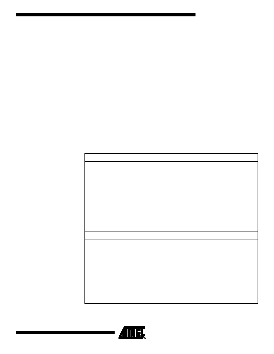
Note:
Assembly Code Example
USART_Init:
; Set baud rate
out
UBRRH, r17
out
UBRRL, r16
; Enable receiver and transmitter
ldi
r16, (1<<RXEN)|(1<<TXEN)
out
UCSRB,r16
; Set frame format: 8data, 2stop bit
ldi
r16, (1<<URSEL)|(1<<USBS)|(3<<UCSZ0)
out
UCSRC,r16
ret
C Code Example
void
USART_Init( unsigned int baud )
{
/* Set baud rate */
UBRRH = (unsigned char)(baud>>8);
UBRRL = (unsigned char)baud;
/* Enable receiver and transmitter */
UCSRB = (1<<RXEN)|(1<<TXEN);
/* Set frame format: 8data, 2stop bit */
UCSRC = (1<<URSEL)|(1<<USBS)|(3<<UCSZ0);
}
发布紧急采购,3分钟左右您将得到回复。
相关PDF资料
PIC16F1828-I/SO
IC PIC MCU 8BIT 14KB FLSH 20SOIC
PIC16F688-I/SL
IC PIC MCU FLASH 4KX14 14SOIC
22-02-3213
CONN FFC/FPC VERTICAL 21POS .100
22-15-3193
CONN FFC/FPC 19POS .100 RT ANG
PIC16C433T-E/SO
IC MCU CMOS 8BIT 10MHZ 2K 18SOIC
22-02-3103
CONN FFC/FPC VERTICAL 10POS .100
PIC16C432T-E/SS
IC MCU CMOS 8BIT 20MHZ 2K 20SSOP
PIC16C432-I/P
IC MCU CMOS 8-BIT 20MHZ 2K 20DIP
相关代理商/技术参数
PIC16F1825-E/ML
制造商:Microchip Technology Inc 功能描述:; Controller Family/Series:PIC16F; Core
PIC16F1825-E/P
功能描述:8位微控制器 -MCU 14KB FL 1KBRAM 32MHz 12I/0 Enhanced Mid RoHS:否 制造商:Silicon Labs 核心:8051 处理器系列:C8051F39x 数据总线宽度:8 bit 最大时钟频率:50 MHz 程序存储器大小:16 KB 数据 RAM 大小:1 KB 片上 ADC:Yes 工作电源电压:1.8 V to 3.6 V 工作温度范围:- 40 C to + 105 C 封装 / 箱体:QFN-20 安装风格:SMD/SMT
PIC16F1825-E/P
制造商:Microchip Technology Inc 功能描述:; Controller Family/Series:PIC16F; Core
PIC16F1825-E/SL
功能描述:8位微控制器 -MCU 14KB FL 1KBRAM 32MHz 12I/0 Enhanced Mid RoHS:否 制造商:Silicon Labs 核心:8051 处理器系列:C8051F39x 数据总线宽度:8 bit 最大时钟频率:50 MHz 程序存储器大小:16 KB 数据 RAM 大小:1 KB 片上 ADC:Yes 工作电源电压:1.8 V to 3.6 V 工作温度范围:- 40 C to + 105 C 封装 / 箱体:QFN-20 安装风格:SMD/SMT
PIC16F1825-E/SL
制造商:Microchip Technology Inc 功能描述:; Controller Family/Series:PIC16F; Core 制造商:Microchip Technology Inc 功能描述:IC, 8BIT MCU, PIC16F, 32MHz, SOIC-14
PIC16F1825-E/ST
功能描述:8位微控制器 -MCU 14KB FL 1KBRAM 32MHz 12I/0 Enhanced Mid RoHS:否 制造商:Silicon Labs 核心:8051 处理器系列:C8051F39x 数据总线宽度:8 bit 最大时钟频率:50 MHz 程序存储器大小:16 KB 数据 RAM 大小:1 KB 片上 ADC:Yes 工作电源电压:1.8 V to 3.6 V 工作温度范围:- 40 C to + 105 C 封装 / 箱体:QFN-20 安装风格:SMD/SMT
PIC16F1825-E/ST
制造商:Microchip Technology Inc 功能描述:; Controller Family/Series:PIC16F; Core 制造商:Microchip Technology Inc 功能描述:IC, 8BIT MCU, PIC16F, 32MHz, TSSOP-14
PIC16F1825-I/ML
功能描述:8位微控制器 -MCU 14KB FL 1KBRAM 32MHz 12I/0 Enhanced Mid RoHS:否 制造商:Silicon Labs 核心:8051 处理器系列:C8051F39x 数据总线宽度:8 bit 最大时钟频率:50 MHz 程序存储器大小:16 KB 数据 RAM 大小:1 KB 片上 ADC:Yes 工作电源电压:1.8 V to 3.6 V 工作温度范围:- 40 C to + 105 C 封装 / 箱体:QFN-20 安装风格:SMD/SMT